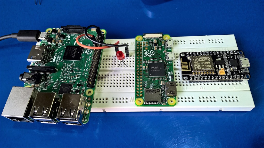
| Blink Series | ESP8266 Series |
Blink in Electronics is Hello World equivalent of Programming. Raspberry Pi like Single Board Computers and Arduino like open source microcontroller boards have made Electronics accessible to even kids and we as professionals can use these platforms to develop software and hardware solutions. As Alan Kay said People who are really serious about software should make their own hardware; with such platforms in market; its not that difficult anymore!
Arduino comes in different shapes and sizes; UNO is one of the more popular boards and recommended for getting started. We connect it to computer over USB and using Arduino IDE write “sketch”; an Arduino program in C like environment that we can then upload and run on the microcontroller seamlessly. Board gets the power from the USB when connected; we can disconnect the USB and power it externally as well. It has all the necessary USB to TTL adapter and power regulation circuitry along with General Purpose Input Output (GPIO) pins where we can connect additional peripherals / hardware / electronics. Arduino IDE has example sketches; and Blink example is there.

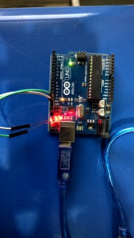
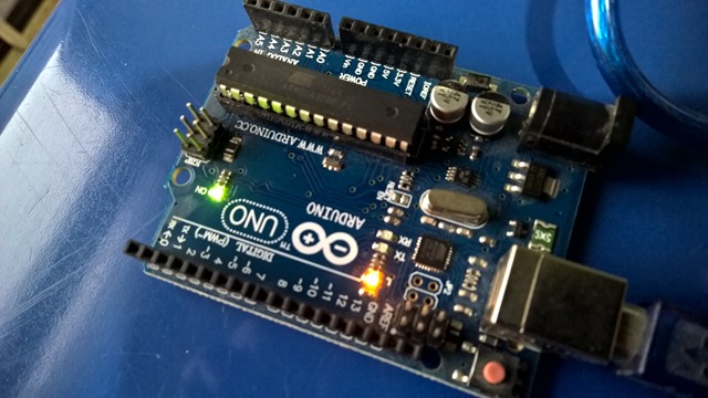 setup() method gets called when the board boots up and loop() keep getting called later on. LED_BUILTIN is constant and on UNO its pin 13 where the on board LED is connected. On one side of UNO are Digital Pins on the other sides are Power pins with different voltages and Analog pins. The pin numbers are labeled and we can connect our LED to any of it and use the number instead of LED_BUILTIN.
- The longer pin of LED is Anode / +ve that needs to be connected to any of the Digital Pin other than Ground (GND) and the shorter pin is Cathode / –ve that needs to be connected to the GND pin
- If we see through the LED; the Anode side is smaller and the Cathode side is flattened.
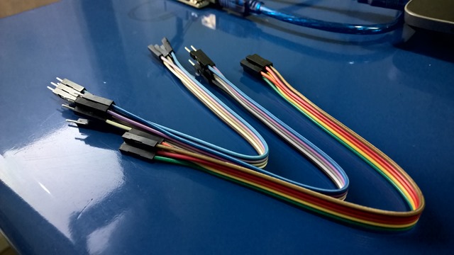
- We need jumper wires that comes in three flavors, female to female, male to male and male to female, we will need male to female wire for connecting LED to Arduino board directly without using the breadboard. For breadboard; we will need male to male!
Arduino is great; the IDE support libraries and there exists many “Shields” / daughter boards for Arduino that provides additional functionality from storing data to SD card to Wifi or Ethernet connectivity etc; there is a great ecosystem around this. There are some limitations like UNO’s ATmega328P Micro Controller is not that speedy and has limited memory; you cannot run complicated “software” on it and adding internet connectivity increases the cost. Thankfully there are many other options like ESP8266 based boards. ESP8266 provides Wifi / TCP-IP stack out of the box and its ESP12 onwards variants are FCC approved and has 1MB to 4MB memory which is quite respectable. NodeMCU is getting quite popular as it comes with a firmware that has Lua scripting support; its ESP12 based and AMICA’s NodeMCU R2 board is Breadboard friendly and comes with USB to TTL and USB Power Regulator circuitry similar to Arduino.
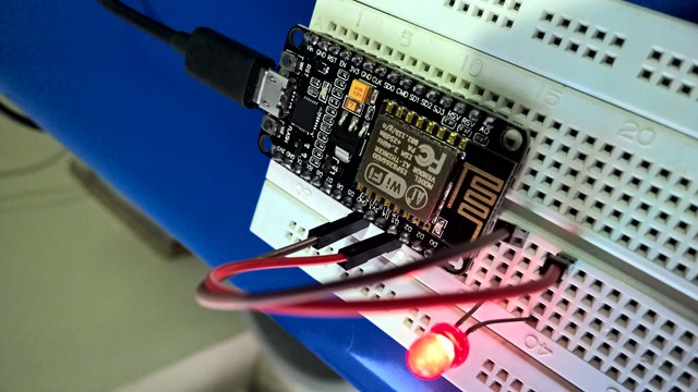
- Watch out; there exists many NodeMCU / ESP8266 boards; http://frightanic.com/iot/comparison-of-esp8266-nodemcu-development-boards/ has nice comparison; NodeMCU AMICA R2 is the respected one and highly recommended board.
- Having a respected board is recommended so that when connected to your computer its USB to TTL adapter drivers gets installed; AMICA R2 comes with CP2102 adapter and it gets detected and drivers get installed seamlessly.
To use the board; we first flash the NodeMCU firmware using https://github.com/nodemcu/nodemcu-flasher; once flashed; we can use ESPlorer; an IDE for ESP8266; similar to Arduino IDE. It supports writing LUA scripts. As per NodeMCU requirement; we need to create init.lua file and upload; and then this script gets executed when the ESP8266 is reset having NodeMCU firmware. Here is one such script which is a webserver giving us the option to On/Off the GPIO0 and GPIO2 ports of the Micro Controller. It will also connect the chip to the wifi network with provided credentials
wifi.setmode(wifi.STATION)
wifi.sta.config("YOUR-WIFI-NETWORK","WIFI-PASSWORD")
print(wifi.sta.getip())
led1 = 3
led2 = 4
gpio.mode(led1, gpio.OUTPUT)
gpio.mode(led2, gpio.OUTPUT)
srv=net.createServer(net.TCP)
srv:listen(80,function(conn)
conn:on("receive", function(client,request)
local buf = "";
local _, _, method, path, vars = string.find(request, "([A-Z]+) (.+)?(.+) HTTP");
if(method == nil)then
_, _, method, path = string.find(request, "([A-Z]+) (.+) HTTP");
end
local _GET = {}
if (vars ~= nil)then
for k, v in string.gmatch(vars, "(%w+)=(%w+)&*") do
_GET[k] = v
end
end
buf = buf.."<h1>ESP8266 Web Server</h1>";
buf = buf.."<p>GPIO0 <a href=\"?pin=ON1\"><button>ON</button></a> <a href=\"?pin=OFF1\"><button>OFF</button></a></p>";
buf = buf.."<p>GPIO2 <a href=\"?pin=ON2\"><button>ON</button></a> <a href=\"?pin=OFF2\"><button>OFF</button></a></p>";
local _on,_off = "",""
if(_GET.pin == "ON1")then
gpio.write(led1, gpio.HIGH);
elseif(_GET.pin == "OFF1")then
gpio.write(led1, gpio.LOW);
elseif(_GET.pin == "ON2")then
gpio.write(led2, gpio.HIGH);
elseif(_GET.pin == "OFF2")then
gpio.write(led2, gpio.LOW);
end
client:send(buf);
client:close();
collectgarbage();
end)
end)
- NodeMCU firmware comes with Lua library for wifi and networking that we are using above to connect to Wifi network and setting up a basic web server and writing data to GPIOs
Once its up we can then access our LUA app and On/Off the GPIO port where we connected our LED
- We can call LUA functions from the IDE; using wifi.sta.getip() we can get the IP address the device has got on the Wifi network
- Arduino started developing non AVR boards; and they modified their IDE to support different tool chains to support these boards using “core”; there exists ESP8266 Arduino Core using which we can use Arduino IDE, its C/C++ based language and many Arduino libraries out in the world to compile “Arduino Sketch” for ESP8266 as well; the ESP8266 Core comes with required libraries for Wifi / Networking capabilities of the MCU (Micro Controller Unit)
NodeMCU / ESP8266 can do a lot in the modern IoT world; there are many devices out there powered with this Micro Controller and we can achieve a lot; from cloud connectivity to auto update-able app + firmware. But if we want the ability to have computer like features in our electronics setup; that we can run many programs; change and debug them remotely; have rich on board computing or need additional software on the board (database / programming environment / custom networking capability) or need some hardware that needs drivers or some custom application (USB camera or similar hardware); Raspberry Pi is the way to go; because one powerful feature of the Raspberry Pi is the row of GPIO pins that provide physical interface between the Pi (Linux and other operating system) and Electronics world
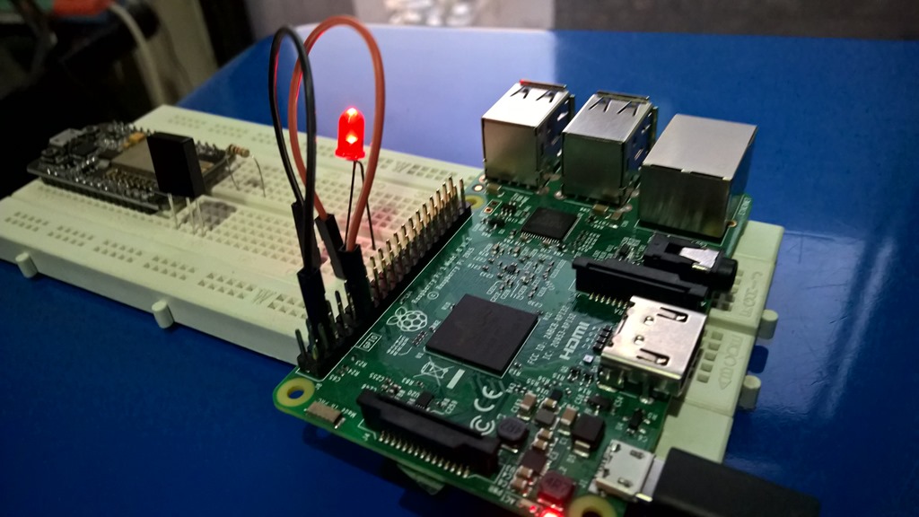
The RPi.GPIO python module offers easy access to the general purpose IO pins on the Raspberry Pi. To install it use apt-get and install python-dev and python-rpi.gpio packages
sudo apt-get install python-dev python-rpi.gpio
Once installed; we can write a simple blink.ph script similar to Arduino above; we set the numbering scheme using GPIO.setmode; there is GPIO.BCM for GPIO Numbering mode and GPIO.BOARD for Physical Numbering.
The GPIO pins are numbered in two ways; GPIO Numbering; the way computer sees them and these jump about all over the place and we need a printed reference for that and the other is Physical Numbering; in which we refer to the pin by simply counting across and down.
There also exists WiringPi; a GPIO C Library that enables us to access our electronics connected to Raspberry Pi from the C/C++ environment in very Arduino like fashion. http://wiringpi.com/download-and-install/ has all the information you need to download and compile it.

Image from http://wiringpi.com/pins; where WiringPi numbering is documented
GPIO0 is physically pin 11 and BCM wise its 17 and in WiringPi its refered to as pin 0. With this information; our blink.ph (Python) and blink.c (C using wiringpi) would be something like this:

- To compile the C file; we will use –Wall and –lwiringPi switches with gcc
Raspberry Pi might feel costlier; but there exists Pi Zero; thats almost NodeMCU size, gives us similar feature of its bigger brother and is NodeMCU like quite affordable. However we will need OTG Ethernet or Wifi dongle in case we need internet connectivity in our project and though total cost might be more than NodeMCU; but having a PC like experience to control the electronics and the freedom that comes due to its Linux based operating system is simply unmatched and it gives much better and wider options in term of manageability when things are in production.
